
Wi-Fi Controlled Robot Car Using Nodemcu and Blynk
We can control the robot car over the internet for infinite range.

 L298 Motor Driver Module 🛒
Software Used:

Getting to Know Your L298N Dual H-Bridge Motor Controller Module .An H-Bridge
- Specifications:
- Double H bridge Driver Chip: L298N
- Logical voltage: 5 V
- Drive voltage: 5V-35V
- Logical current: 0-36mA
- Drive current: 2 A (MAX single bridge)
- Max power: 25W
- Note: Built-in 5v power supply, when the driving voltage is 7v-35v. But i recommend you not to power up your microcontroller with on-board 5v power supply.
1: connect the bo motor to the motor driver as shown
2: connect the motor driver to nodemcu as given below:
- GPIO2(D4)- IN3
- GPIO15(D8)-IN1
- GPIO0(D3)-IN4
- GPIO13(D7)-IN2
- GPIO14(D5)-Enb-A
- GPIO12(D6)-Enb-B
3:Supply Connections :
- +12v - Positive terminal of the battery to be connected.
- GND - Ground terminal of the battery to be connected.
- +5v - +5v input (unnecessary if your power source is less than +7v to +9v, if the power source is greater than +9v to +35v then it can act as a 5v out)
- 4:Input Connections :
- (Motor A) ENA - Enables PWM signal for Motor A
- IN1 -Enable Motor A
- IN2 - Enable Motor A
- (Motor B) ENB - Enables PWM signal for Motor B
- IN3: Enable Motor B
- IN4: Enable Motor B
Note : Make sure you have all of your grounds connected together. (NodeMCU, Power Source, and Motor Driver)The PWM Pins are unnecessary if
- Download the Blynk app from the google play store
- Sign in with a valid E-mail address
- Create a new project

- Give Project a name and choose NodeMCU as the device from the list
- Then choose WIFI as the connection type and press create
- An Auth Token will we generated an sent to the Email address which you signed in
- Copy and save the Auth Token somewhere save and will we used in upcoming steps

- Now click "+" to add widgets, then add a Joystick and Slider .now the Joystick is displayed on the dashboard

- Then click on the Joystick widgets from the dashboard to edit the Joystick settings

- select the virtual pin v1 because
I even have written the code for v1 and slide the button from split to merge - set
the worth range from 0-1023 because it helps in easy control of robot for larger values

- now select the slider , select the virtual pin v2,and set values from 0 - 1023.
- Click on the Icon to open the Arduino window
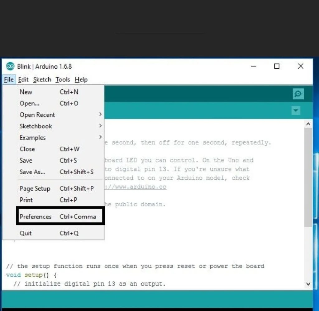
- Open the File and click on the Preferences
- Adding ESP8266 Board Manager

- In the Additional Boards Manager enter below URL. http://arduino.esp8266.com/stable/package_esp8266... As highlighted in the figure and enter OK.
- Selecting Board
Now open the tools
- ESP8266 Board Package
The Boards Manager window opens, scroll the window page to bottom till you see the module with the name ESP8266. Once we
- Selecting ESP8266 Arduino Board
To run the esp8266 with Arduino
- Connecting ESP8266 to the PC
Now Let’s connect the ESP8266 module to your computer through USB cable as shown
STEP 3: Programming NodeMCU
#include <Esp8266Wifi.h>
#include<BlynkSimpleEsp82666.h>
/* define L298N or L293D motor control pins */
int leftMotorForward = 2; /* GPIO2(D4) -> IN3 */
int rightMotorForward = 15; /* GPIO15(D8) -> IN1 */
int leftMotorBackward = 0; /* GPIO0(D3) -> IN4 */
int rightMotorBackward = 13; /* GPIO13(D7) -> IN2 */
int z;
/* define L298N or L293D enable pins */
int rightMotorENB = 14; /* GPIO14(D5) -> Motor-A Enable */
int leftMotorENB = 12; /* GPIO12(D6) -> Motor-B Enable *
/ You should get Auth Token in the Blynk App. // Go to the Project Settings (nut icon).
// Use your own WiFi settings
char auth[] = "**********";
char ssid[] = "type your network name here ";
char pass[] = "type your network password here";
// neutral zone settings for x and y
// joystick must move outside these boundary numbers to activate the motors
// makes it a little easier to control the wifi car
int minRange = 312;
int maxRange = 712;
// analog speeds from 0 (lowest) - 1023 (highest)
// 3 speeds used -- 0 (noSpeed), 350 (minSpeed), 850 (maxSpeed).
// use whatever speeds you want...too fast made it a pain in the ass to control
int minSpeed = 450;
int maxSpeed = 1023;
int noSpeed = 0;
void moveControl(int x, int y) {
// movement logic // move forward
// y je vetsi jak maxrange a současně x je vetsi jak minRange a současne mensi jak max range
if(y >= maxRange && x >= minRange && x <= maxRange) {
analogWrite(leftMotorENB,z);
analogWrite(rightMotorENB,z);
digitalWrite(leftMotorForward,HIGH);
digitalWrite(rightMotorForward,HIGH);
digitalWrite(leftMotorBackward,LOW);
digitalWrite(rightMotorBackward,LOW); } //MOVE FORWARD RIGHT
else if(x <= minRange && y >= maxRange ) {
digitalWrite(leftMotorENB,maxSpeed);
digitalWrite(rightMotorENB,minSpeed);
digitalWrite(leftMotorForward,HIGH);
digitalWrite(rightMotorForward,HIGH);
digitalWrite(rightMotorBackward,LOW);
digitalWrite(leftMotorBackward,LOW); } // move right
else if(x >= maxRange && y >= minRange && y<=maxRange)
{ analogWrite(leftMotorENB,z);
analogWrite(rightMotorENB,z);
digitalWrite(leftMotorForward,HIGH);
digitalWrite(rightMotorForward,LOW);
digitalWrite(rightMotorBackward,HIGH);
digitalWrite(leftMotorBackward,LOW);
}
// move forward LEFT
else if(x <= minRange && y >= maxRange ) {
digitalWrite(leftMotorENB,minSpeed);
digitalWrite(rightMotorENB,maxSpeed);
digitalWrite(leftMotorForward,HIGH);
digitalWrite(rightMotorForward,HIGH);
digitalWrite(rightMotorBackward,LOW);
digitalWrite(leftMotorBackward,LOW); }
// moveleft else if(x <= minRange && y >= minRange && y <= maxRange) {
analogWrite(leftMotorENB,z);
analogWrite(rightMotorENB,z);
digitalWrite(leftMotorForward,LOW);
digitalWrite(rightMotorForward,HIGH);
digitalWrite(rightMotorBackward,LOW);
digitalWrite(leftMotorBackward,HIGH); }
// neutral zone
else if(y < maxRange && y > minRange && x < maxRange && x > minRange)
{ digitalWrite(leftMotorENB,LOW);
digitalWrite(rightMotorENB,LOW);
digitalWrite(leftMotorForward,LOW);
digitalWrite(leftMotorBackward,LOW);
digitalWrite(rightMotorForward,LOW);
digitalWrite(rightMotorBackward,LOW); }
// move back
else if(y <= minRange && x >= minRange && x <= maxRange) {
analogWrite(leftMotorENB,z);
analogWrite(rightMotorENB,z);
digitalWrite(leftMotorBackward,HIGH);
digitalWrite(rightMotorBackward,HIGH);
digitalWrite(leftMotorForward,LOW);
digitalWrite(rightMotorForward,LOW); }
// move back and right
else if(y <= minRange && x <= minRange) {
digitalWrite(leftMotorENB,maxSpeed);
digitalWrite(rightMotorENB,minSpeed);
digitalWrite(leftMotorForward,LOW);
digitalWrite(rightMotorForward,LOW);
digitalWrite(rightMotorBackward,HIGH);
digitalWrite(leftMotorBackward,HIGH); }
// move back and left
else if(y <= minRange && x >= maxRange) {
digitalWrite(leftMotorENB,minSpeed);
digitalWrite(rightMotorENB,maxSpeed);
digitalWrite(leftMotorForward,LOW);
digitalWrite(rightMotorForward,LOW);
digitalWrite(rightMotorBackward,HIGH);
digitalWrite(leftMotorBackward,HIGH); } }
void setup() {
// initial settings for motors off and direction forward
pinMode(leftMotorForward, OUTPUT);
pinMode(rightMotorForward, OUTPUT);
pinMode(leftMotorBackward, OUTPUT);
pinMode(rightMotorBackward, OUTPUT);
/* initialize motor enable pins as output */
pinMode(leftMotorENB, OUTPUT);
pinMode(rightMotorENB, OUTPUT);
Blynk.begin(auth, ssid, pass); }
void loop() {
Blynk.run(); }
BLYNK_WRITE(V1)
{ int x = param[0].asInt();
int y = param[1].asInt();
moveControl(x,y); }
BLYNK_WRITE(V2)
{ z = param[0].asInt(); } // code end here
HOPE U WOULD HAVE CREATED THIS PROJECT!!!
Comments
Post a Comment
If you have any doubts ,Please let me know.